Technical Guides
2 min read
2/28/2026
Expansion Joint Anchorage Design: Resisting Uplift, Lateral, and Fatigue Forces
By Engineering Team
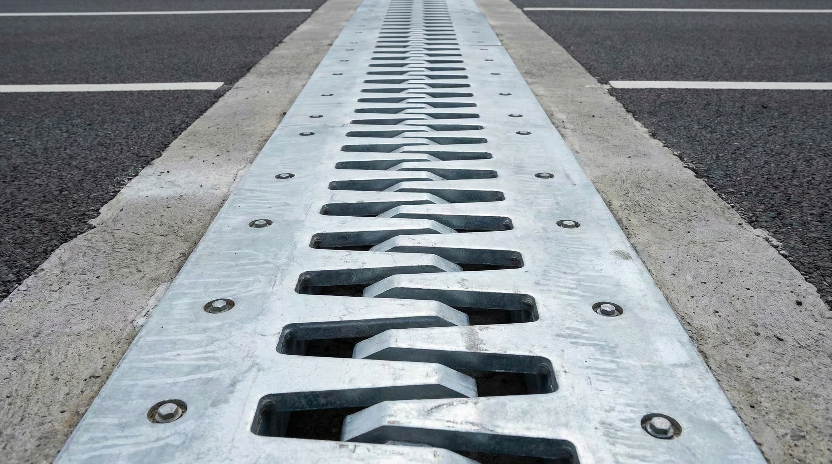
Expansion joint anchorage must resist complex loading including uplift from vehicle impact, lateral forces from braking and seismic loads, and fatigue from millions of traffic cycles.
Loading Cases for Anchorage Design:
Vertical Load (Dominant): Design wheel load 100-500 kN/m depending on bridge class. Dynamic amplification factor 1.3-1.5 (highway), 2.0-2.5 (high-speed rail). Uplift from impact: 30-50% of vertical load.
Lateral Load: Braking force 10% of vertical load (longitudinal). Seismic force from response spectrum analysis. Thermal restraint minimal for properly designed joints.
Fatigue Loading: Design for 100 million cycles (50-year life at 2 million vehicles/year). Fatigue stress range per EN 1993-1-9 or AASHTO fatigue categories. Critical details: Anchor bolt threads, weld toes, edge beam connections.
Anchor Bolt Design: Minimum bolt diameter M24 (24mm) for highway bridges. Embedment depth minimum 10x bolt diameter (240mm for M24). Spacing 200-400mm centers. Material Grade 8.8 or stainless steel A4-70. Grouting: Epoxy adhesive anchor (preferred) or cast-in anchor.
Concrete Substrate Requirements: Minimum concrete strength C30/37 (EN) or 4000 psi (AASHTO). Additional reinforcement required around anchor zone. Minimum 50mm cover to anchor bolts.